Tuesday 18 October 2011

Various Jobs

The front suspension has now been put back together after fitting the new rubber boots to all the ball joints. I've since started to make a panel for the back shelf using some 4mm black pp sheet.


Tonight, I made some brackets from stainless plate which support the handbrake cables. These are positioned either side so that the cables are well clear of all the chassis rails and won't come into contact with the top wishbones. I noticed these flex a little when activating the handbrake so the plan is to swap the rivets out for bolts through the box section.

Thursday 13 October 2011

Ball joints

For some reason, the rubber boots for the ball joints, track rods ends and drag links had all perished even though the car has been sat in the garage since the start of the build. Rather than buy new joints, I found some replacement rubber boots which were delivered over the weekend so the evenings this week has been spent replacing the old boots with the new ones. This meant jacking the front up again and removing the uprights to get the joints off. At the same time, I took the opportunity to paint the uprights again, this time with POR15 as the sprayed on hammerite was showing signs of rust coming through. I should get round to putting it all back together again over the weekend and the plan is to fit the cycle wing brackets at the same time so I can start to work on these and get the front wings on.

Sunday 9 October 2011

Wiring nearly finished

The front indicators have now been wired up. I decided to use some connector plugs so then if I need to remove the nose cone at a later date, it won't mean needing to cut through the wires.


The wires under the dash have been tidied up using some cable ties. I also moved one of the fuse boxes so that the wires coming out of the back aren't being squashed over. The wires the other side of the aluminium panel have been secured down and held together using more cable ties and loom tape. I had a general tidy up in the engine and found the battery lead's protection had been overlooked so these are now covered by split conduit.


This just leaves the headlights to wire in. I need to figure out the best way to protect the threads underneath so that they don't fall foul of the radius test at IVA. All I've done so far is offer up some track rod covers which look like they'll do the job quite nicely. I'll try and get the headlight alignment done as best as possible beforehand. I need to read up on these lamps in general as I saw somewhere needing to rotate the glass by a few degrees to get the dip beam pattern correct.


Tuesday 4 October 2011

Dashboard finished

After researching where best to position the digidash, there seemed to be three main options
1) Behind the steering wheel
2) Middle of the dash but recessed so the surface is flush
3) Within the IVA exclusion zone around the steering wheel

I dismissed the first idea as I couldn't see an easy way to mount the digidash plus the wires to the rear would be exposed. I then dismissed option three as this would mean cutting a hole free hand and I wasn't convinced I'd make a tidy job of it so I opted for the third method.

Using masking tape and a square, I marked out the steering wheel radius and then marked another radius 127mm out. Then, whilst sitting in the drivers seat marked a position to mount the digidash making sure I could see the speedo panel. The dremel was used to make a square shaped hole for the loom connector and three more holes to allow the digidash to sit against the dashboard. After mounting the digidash using the supplied screws the dashboard was then offered up to the scuttle. At this point, I realised I could see the speed reading but - only through my left eye! The steering wheel rim blocked the view when looking through my right eye. Feeling rather annoyed I did what was probably best and sulk off for a beer and to sleep on it.


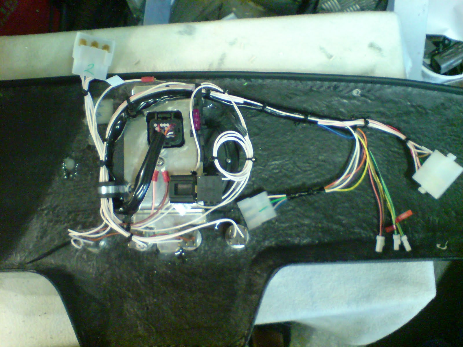
The next morning, I'd decided I should have gone for option 2 from the beginning. The holes I'd made the previous evening were filled with araldite, the dash wrapped with di-noc and a hole cut. Some U trim was applied to the hole to neaten the edges and an aluminium bracket made up to support the digidash. With this in place, I set to wiring up the savage switches with three multi connector plugs to allow for easy connection and removal if required. I'd used some sikaflex to attach some cable tie bases to the back of the dash so that the wires do not hang down.

How digidash is mounted now:


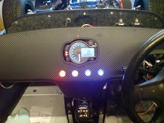
The savage switches from left to right are low brake fluid /test, side lights, fog light switch and fan over-ride switch.

I also needed to extend the speedo cable and water temp cables to connect to the Koso dash. Most of the wiring is now done apart from the front lights and a general tidy up underneath the scuttle.


=====================

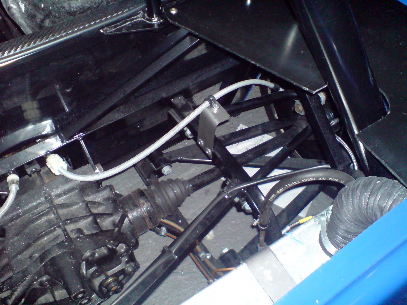
To whoever it was that asked about the speedo sensor - I fixed a magnet to one of the drive shafts and using a bracket then pointed the Koso sensor at the magnet. I did reply to your query/comment on this blog but it wouldn't publish my reply (I tried twice! - don't know whats happened to blogspot but its been a pain in the backside to use recently)